Home > Medical Training Manuals > Dental Volume 2 > Internal Components Of A Large Automatic Processor
maintenance described next are for the specific processor shown. If you work with a different make or model of an automated processor, refer to that manufacturer's operational manual for operating instructions.
Figure 1-45 shows the main external components of the large automatic film processor. Figure 1-46 shows the internal components when the top cover is opened from the processor. Figure 1-47 shows the functions of the operator’s control panel.
The daily operational check of the large automatic processor is performed as follows:
1. Plug the power supply cable into the power outlet.
2. Check the solutions. Most automatic processors are equipped with a replenisher, which automatically replenishes solutions when the power is turned on. An automatic processor without an automatic replenisher requires that you manually replenish the developer and fixer solutions. Pour the solutions slowly to avoid splashing. Direct the pouring stream to the center of the tank away from the drain tubes.
3. Turn on the external water supply valve. This valve is normally located close to and above the automatic processor. If not equipped with external water supply, change the water in wash water container and refill with fresh water.
4. Activate the automatic processor by depressing the power on switch. If equipped with an automatic replenishing system, the internal oscillating pumps will now cycle and fill the solution tanks to their proper levels. When the low solution level lamp has gone out, the solution heater will start and the transports will turn. Do not process films at this time.
5. After 10 to 15 minutes, The ready lamp will illuminate. This indicates that the proper processing temperature has been reached.
6. Depress the run/standby switch to the run position. Insert an 8-inch x 10-inch cleaning film into the processor receiving tracks. The cleaning film cleans the rollers of accumulated deposits, dirt, and debris. Use a new cleaning film every week. After the cleaning film exits the processor, depress the run/standby switch to the standby position.
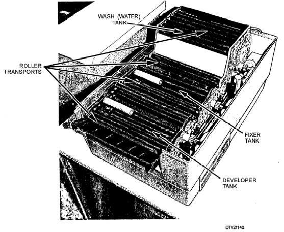
Figure 1-46. - Internal components of a large automatic processor.
Continue Reading