Control System
This system delivers the drive air and coolant to whichever handpiece is lifted from the dental unit. The control system is made up of two parts: handpiece controls and a foot control.
HANDPIECE CONTROLS. - Most handpiece controls are located on the bracket tray that can accommodate three handpieces (fig. 11-6). The water coolant flow and maximum drive pressure are individually adjustable for each handpiece.
Most units use the following international symbols:
A blue dot identifies a water control.
A yellow dot identifies an air control.
A red dot identifies the ON or active position.
Every dental unit has a master ON-OFF toggle or switch. It turns on the air and water to the control system. When it is turned off, none of the items on the unit will function. This switch should be OFF whenever the unit is not in use to prevent flooding in the event of a leak while the system is unattended. The ON/OFF indicator provides a visual indication that the system is pressurized when the master switch is ON.
HANDPIECE HOSES. - The handpiece hose is attached to a coupling that joins the handpiece to the hose. Never over-tighten the coupling. Under- tightening
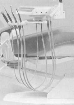
Figure 11-6. - Handpiece controls.
can cause air and waterleaks. Many providers use a "quick disconnect" that attaches to the coupling. By gently pulling on the handpiece, the operator is able to change handpieces very quickly. The quick disconnect is also available with a 360° swivel that allows the handpiece to be turned around without tangling up the hoses. Perform a daily operational check on the quick disconnect equipment. Inspect "O" rings and replace them if found frayed or missing.
FOOT CONTROL. - All handpieces are operated by the provider through the use of a foot control (rheostat) device. A valve inside the foot control regulates the handpiece speed and provides an air signal that activates the air and water coolant flow. The foot control is operated by light foot pressure applied to any part of the disk. Some foot controls may also be equipped with a wet/dry toggle switch and a chip blower. The wet/dry toggle switch can shut off the water coolant to the handpiece without moving the hands from the treatment area. The chip blower sends a jet of air through the handpiece when not in use to remove any debris accumulated in the treatment site.
Other Controls
The other controls that could be on the bracket table and assembly, depending on the make and model, are as follows:
WATER COOLANT ON/OFF TOGGLE - Stops the flow of water coolant to all handpieces.
AIR COOLANT FLOW CONTROL - Adjusts the air coolant flow to all handpieces and can completely shut off the air coolant.
DRIVE AIR PRESSURE CONTROL - Adjusts the drive air pressure to the handpiece with an adjustment screw for each handpiece.
SYRINGE FLOW CONTROL - Adjusts the air and water flow from the three-way syringe.
AUTOMATIC HANDPIECE HOLDER - Shuts off air and water to the handpiece when it is in the holder.
HANDPIECE TUBING FLUSH SYSTEM - Some newer models of dental units have a handpiece tubing flush system that quickly and thoroughly flushes the handpieces to wash away contaminants accumulated in the handpiece and tubing. This system saves wear on the handpieces by sending water directly to the handpiece, and bypassing the control block and not requiring the handpiece turbine to operate. Flush the handpieces at the beginning of each day for
Continue Reading